Atmospheric Pressure Ionization Waves Propagating Through a Flexible High Aspect Ratio Capillary Channel and Impinging upon a Target
I. Introduction
Combining therapeutic effects and minimum tissue damage, cold, atmospheric pressure plasmas (CAPPs) are being investigated for many biomedical applications such as sterilization, wound healing, cell manipulation and cancer therapy. The generation and propagation of CAPPs in long, flexible capillary tubes having large aspect ratios not only have direct applications, such as catheter sterilization, but are also an important way of transporting plasma and its active species to remote targeted areas. The goal of this study is to clarify the mechanisms for propagation of ionization waves (IWs) inside capillary tubes of arbitrary length and path (e.g., tubing with loops and bends) through numerical simulation.
II. Description of the Model and Discharge Configuration
The numerical modeling platform used in this study is nonPDPSIM, a 2-dimensional plasma hydrodynamics model with radiation-photon transport. Continuity equations for charged and neutral species, and Poisson's equation are solved coincident with the electron energy equation with transport coefficients obtained from solutions of Boltzmann's equation. The photon transport is based on a propagator or Green's function method which accounts for obstructions. The spatial discretization is based on finite volume methods using an unstructured mesh. The time advancement is implemented with a fully implicit Newton iteration method.
The discharge configuration consists of the powered and grounded electrodes, dielectric capillary channel and the target chamber, as shown in Fig. 1. The channel is 600 μm wide, about 15 cm long (aspect ratio 250) and consists of 7 sections with different radii of curvature. The channel wall has a uniform thickness of 600 μm and a dielectric constant εr = 4. Both the channel and the target chamber are filled with Ne at 1 atm with a trace impurity of 0.01% Xe. The full computational domain is a 12 cm square and is grounded on the side (x = 0 and 12 cm) and bottom (y = 0 cm) boundaries. The top boundary (y = 12 cm) consists of the target layer which is 2 mm thick and has the same dielectric properties as the channel wall. A constant high voltage (25-50 kV) pulse of either positive or negative polarity with a rise time of 20 ns is applied to the needle inserted at the beginning of the channel. The total simulation time is 300 ns.
|
Figure 1. Discharge configuration of ionization waves propagating through a flexible, dielectric capil-lary channel and impinging upon a target. (a) The capillary channel is 600 μm wide and about 15 cm long. b) The ionization waves are initiated by a needle powered electrode and an annular ring at the beginning of the channel. |
III. Ionization Waves in the Capillary Channel
For both positive and negative polarities, IWs, initiated at the start of the channel, are able to propagate through the entire 15 cm channel length while maintaining nearly constant plasma characteristics and speed with a factor of two. Only positive polarity cases are shown here. The IW exiting the capillary tube triggers a conventional streamer inside the target chamber which then impinges onto the surface. Upon striking the surface the IW splits into two side-travelling ionization fronts. Animations of the electron density ne and electron temperature Te for the positive ionization wave and streamer discharge are shown in Fig. 2a-b. The speed of the IW is about 1-3 x 107 cm/s. Throughout the length of the capillary, the ne is approximately 5 x 1013 cm-3 – 1 x 1014 cm-3 and the maximum Te is around 7.5 eV. The confinement of the channel walls gives rise to a much slower variation of the Te following the ionization front. For example, it takes several cm of plasma column trailing the ionization front before Te drops to 1 eV.
a)
|
b)
|
Figure 2. Electron density (a) and electron temperature (b) contours for the positive ionization wave (50 kV) and streamer discharge, Time=0-250ns, Max. ne = 1 x 1014 cm-3, Log scale with over 3 decades. Max. Te=7.5eV. |
|
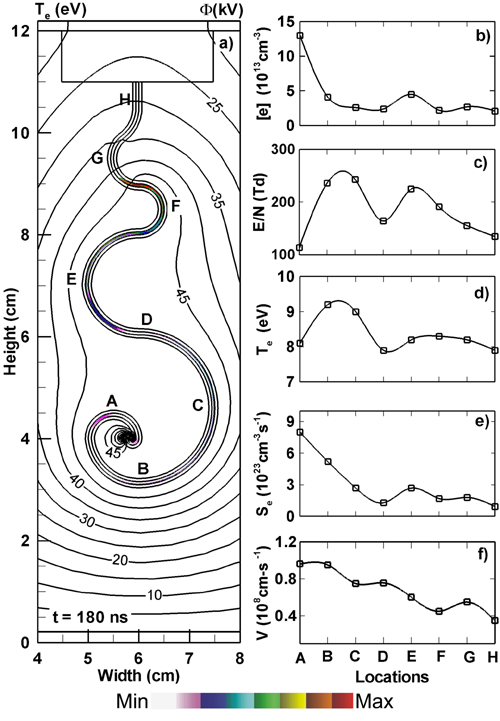
As the ionization wave passes through the capillary channel, its properties are modulated by the curvature of the channel. The electron density ne, normalized electric field E/N, electron temperature Te, electron impact ionization source function Se and instantaneous wave speed vw as the wave front passes (marked as A-H in Fig.1) are in Fig. 3b-f. Despite a general decreasing trend, the ionization wave in the capillary largely maintains its strength and magnitude within about a factor of 2-3. This decrease is largely a result of the increasing voltage drop across the plasma along the length of the tube as the plasma column extends inside the channel.
|
Figure 3. Properties of a positive IW generated by a 50 kV voltage pulse. (a) Contours of electron temperature (flood) and electric potential (lines) at t = 180 ns. Te has a long extended tail of many cm following the ionization front inside the capillary. Quantities characterizing the ionization wave as it passes through different channel locations (points A-H) are shown at the right: b) electron density, c) reduced electric field , d) electron temperature, e) ionization source function and f) instantaneous speed. |
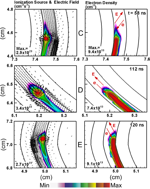
Inside the channel, the peaks of the Se and ne tend to propagate along the walls of the channel rather than filling the channel. They also tend to switch to the opposite side of the wall when the curvature of the channel changes. Se, electric field and ne are shown in Fig. 4 as the positive IW front passes through points C, D and E, where the channel curvature changes from positive to nearly zero to negative. The peak locations of the ionization and electron density change from the inner (left) wall at the point C to the middle at D and finally to the outside (right) wall at E. This change of the locations of the IW coincides with the change of the relative orientation between the electric field in front of the IW and the local capillary channel itself. The peak ionization and electron density occur at the wall where the local electric field points away from the wall and into the plasma, such as point C and E. When the local electric field is aligned with the channel, such as at point D, the ionization peaks moves to the center of the channel.
|
Figure 4. IW properties as at different locations in the channel for a positive voltage 50 kV as the ionization wave passes through points C, D, E (top to bottom). a) Ionization source function and electric field; and b) electron density. The arrows on the electron density plots show the orientation of the instantaneous electric field in front of the IW and the drift direction of the photo-electrons. The contours for ne and Se are plotted on a log scale over 4 decades. |
IV. Streamers in the Target Chamber
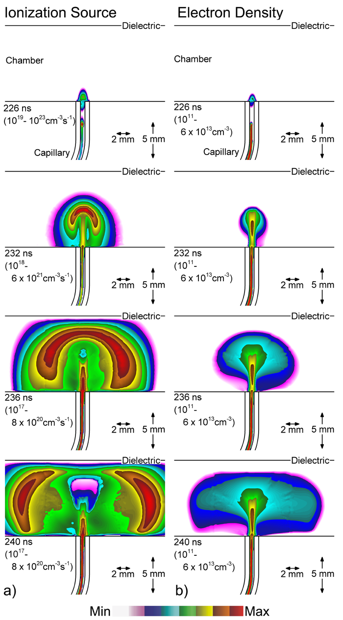
When the IW exits the channel into the target chamber, it brings a large fraction of the applied potential to the junction of the channel and chamber. For the positive polarity, a positive streamer is produced in the chamber at t = 226 ns, seeded by photoionization from the approaching IW in the channel. Se and ne are shown in the target chamber in Figs. 5 for a positive voltage. Before the streamer impinges on the dielectric surface of the target, the region of ionization rate is fairly localized, as in a conventional streamer. The electron density in the chamber has an elongated, jet-like core well aligned with the channel exit with a circular outer distribution. The streamer speed in the chamber reaches about 1 x 108 cm/s, about twice the speed of the IW at point H in the channel. However, the electron density in the chamber is less than that in the channel. The impingement of the streamer charges the target surface and splits the streamer into two which then propagates sideways with similar intensity.
|
Figure 5. Development of streamer discharge in the target chamber induced by the approaching ionization wave of positive polarity from the capillary channel. (a) Ionization source function Se and (b) electron density ne at times of 226, 232, 235 and 240 ns. The contours are plotted on a log scales over the indicated ranges. |
V. Concluding Remarks
A numerical study of atmospheric neon ionization waves propagating through a circuitous capillary, high aspect ratio channel and impinging upon a target has been conducted. The ionization waves, initiated at the beginning of the channel by high voltage (±50kV) pulses are able to propagate through the entire channel length while maintaining their magnitude and speed within factors of 2-3, and upon exiting, trigger streamer discharges in the target chamber which then impinge upon the target surface. Unlike the plasma bullets in open configurations, the IW fronts in the capillary channel are followed by an extended tail of high electron temperature and ionization up to several cm long. The peaks of the ionization source function and electron density tend to propagate along one of the walls if there is any asymmetry rather than filling the channel. The IW also tends to switch to the opposite side of the wall when the channel curvature changes.