![]()
Investigation of Three Dimensional Neutral Flow Effects In an Inductively
Coupled Plasma Reactor Using a New Ambipolar Acceleration
Technique*
Eric R. Keiter and Mark J. Kushner
Department of Electrical & Computer Engineering
University of Illinois at Urbana-Champaign
1406 W. Green St., Urbana, IL 61801
1. Introduction
Optimization of plasma processing devices requires that the flux of reactive species to the work surface be as uniform as possible. Azimuthal asymmetries of the fluxes of reactive neutral and ion species to the wafer are often found in plasma processes, even in reactors that have a high degree of structural azimuthal symmetry. It has been shown that that transmission line effects in the antenna of an Inductively Coupled Plasma (ICP) reactor can be one source of asymmetry in ion fluxes [1]. Given that gas pressures are typically low in processing reactors (10’s of mTorr), gas injection and pumping are often not considered to be significant contributors to azimuthal process nonuniformity, because of the rapid diffusion averaging of sources and sinks. Numerically predicting such asymmetries require a three-dimensional (3d) simulation tool which is capable of resolving both the plasma and the neutral flow that evolve in such systems. This requires that the simulation be able to resolve a wide range of time scales. Until recent years, such 3d tools were not feasible, given the computational resources required.
To address this issue, we have incorporated a new ambipolar acceleration technique into a 3d plasma equipment model, HPEM-3D [1]. This technique allows for times steps long enough to run a neutral fluid flow to convergence, while providing an adequate approximation for the behavior of the charged species. Typically numerical plasma models are subject to several time step constraints. The stringent of which is usually the Dielectric Relaxation Time (DRT), which is given by:
![]() (1)
(1)
where ![]() is the plasma
conductivity and
is the plasma
conductivity and ![]() is the permittivity of free space. If using a
fully explicit Poisson’s equation to obtain the potential, the DRT requires time
steps on the order of ~1.0 x 10⁻¹² s. One can avoid the DRT altogether by using
a fully implicit scheme, in which the plasma transport and Poisson’s equation are
solved simultaneously using a Newton method [2], but this is a difficult numerical problem
to solve, and not feasible for three dimensional problems. A reasonable compromise is
obtained by using a semi-implicit Poisson’s equation, in which the source term in
Poisson’s equation is an estimate of future charge density. [3] By using a
semi-implicit Poisson solution to obtain the potential, the DRT restriction is relaxed,
and the time step constraint becomes of order ~1.0 x 10⁻⁹ s.
is the permittivity of free space. If using a
fully explicit Poisson’s equation to obtain the potential, the DRT requires time
steps on the order of ~1.0 x 10⁻¹² s. One can avoid the DRT altogether by using
a fully implicit scheme, in which the plasma transport and Poisson’s equation are
solved simultaneously using a Newton method [2], but this is a difficult numerical problem
to solve, and not feasible for three dimensional problems. A reasonable compromise is
obtained by using a semi-implicit Poisson’s equation, in which the source term in
Poisson’s equation is an estimate of future charge density. [3] By using a
semi-implicit Poisson solution to obtain the potential, the DRT restriction is relaxed,
and the time step constraint becomes of order ~1.0 x 10⁻⁹ s.
In addition to the DRT, finite-difference schemes of fluid (both plasma and neutral) transport are also constrained by the Courant-Fredrichs-Lewey (CFL) criterion, defined by:
![]() (2)
(2)
This is dependent upon mesh size and the maximum velocity of the system. Electrons are usually the species with maximum velocity in a plasma simulation, and in a simulation for which a mesh cell is 0.5 cm across, the CFL limit will be of order ~1.0 x 10⁻⁹ s, similar to the DRT limit for the semi-implicit case.
Unfortunately, neutral fluid flows reach convergence on the order of 10’s of ms. If limited to a timestep of 1.0 x 10⁻⁹ s, a simulation which accurately resolves the flow of neutral species will require 10’s of thousands of timesteps. For a three-dimensional simulation this is impractical. The purpose of adding the ambipolar acceleration to the HPEM-3D was to circumvent this limitation.
In this paper we present the results of a study which takes advantage of this new acceleration technique and uses the HPEM-3D to determine the effects of asymmetrical gas injection and gas pumping in an Inductively Coupled Plasma (ICP) reactor. We found that both asymmetrical injection and pumping can strongly influence reactant flux nonuniformity to the wafer surface, but that the effects of each could be distinctly different for the chemical systems that we studied. We also studied the effects of introducing impurities into the system through a single injection nozzle.
2. Computational Model
The model that we used for the study is the HPEM-3D, which has been described in some detail in Ref. 1., so we will only describe the new features here. A flowchart of HPEM-3D is shown in Fig. 1 where the new ambipolar acceleration module is shown in the kinetics/fluid module. The ambipolar module provides an estimate of the electrostatic potential using a numerical technique which is not restricted by the dielectric relaxation time. As the ambipolar technique is not limited by dielectric relaxation, it is possible to take time steps that are approximately an order of magnitude larger than one is forced to take if using an implicit Poisson solver to obtain the potential. As a neutral flow typically converges on the order of 10’s of ms, this is a significant advantage.
The assumptions of the ambipolar module are as follows. 1) The electrostatic potential must maintain a summed charged species divergence, which is equal to zero. 2) The electron density and electron fluxes are fixed to the sum of the ion densities. The first assumption results in the following equation:
If this equation is discretized on a Cartesian mesh can be rewritten as:
![]() (4)
(4)
The terms of these equations are illustrated in Fig. 2, a graphical
representation of the discretized form. ![]() is the number of charged
species.
is the number of charged
species. ![]() is the charge of species
is the charge of species ![]() .
. ![]() is the flux of species
is the flux of species ![]() through face
through face ![]() of the
numerical cell.
of the
numerical cell. ![]() is the source of species
is the source of species ![]() . ai is the area of face
. ai is the area of face ![]() , and
, and ![]() is the volume of the
cell.
is the volume of the
cell.
The charged species flux is approximated by drift-diffusion transport. Substituting the drift diffusion expression for charged species flux into Eq. 3, one obtains:
![]() (5)
(5)
![]() is the density and
is the density and ![]() is
the mobility of species
is
the mobility of species ![]()
![]() . This equation can be rearranged into an equation of the same form as
Poisson’s equation:
. This equation can be rearranged into an equation of the same form as
Poisson’s equation:
![]() (6)
(6)
where
![]() (7)
(7)
![]() (8)
(8)
![]() (9)
(9)
Since this equation has the same form as Poisson’s equation, it can be solved using the same numerical techniques. We solve it using Successive Over-Relaxation (SOR), with an optimized relaxation parameter of 1.7. Extending the Poisson’s Equation analogy, term a of Eq. 6 is the analogue of the dielectric permittivity, term b of Eq. 6 is the analogue of the charge density and term c is an analogue of a fixed charge. The equation is therefore not directly sensitive to changes in charged species density, but rather changes in charged species fluxes, which are a more stable quantity.
One potential drawback of using this approach to obtain the electrostatic potential is the lack of sheath resolution. Neither of the assumptions upon which the ambipolar approximation is based will hold in the sheath region, so unlike Poisson’s equation, Eq. 6 will not resolve the sheath for any degree of mesh resolution. To account for the sheath voltage drop, we have incorporated a sheath model into the solution of Eq. 6. The sheath model is based on the standard floating sheath model from probe theory [3]. The voltage drop is calculated from the following equation:
 (10)
(10)
which results from setting the sheath edge ion flux equal to the
electron flux at the wall. ![]() is the sheath potential,
is the sheath potential, ![]() is the electron temperature,
is the electron temperature, ![]() the electron density, and
the electron density, and ![]() the electron mass.
the electron mass. ![]() is the number of ion
species and
is the number of ion
species and ![]() the density of ion species
the density of ion species ![]() , and
, and ![]() is the velocity of ion species
is the velocity of ion species ![]() .
The ion velocity is maximum of the velocity calculated by the fluid model and the Bohm
velocity. Eq. 10 is evaluated for all the plasma domain mesh points which neighbor wall
mesh points, and for these mesh points the additional potential drop is incorporated into
the difference equation in the same manner as this one dimensional example:
.
The ion velocity is maximum of the velocity calculated by the fluid model and the Bohm
velocity. Eq. 10 is evaluated for all the plasma domain mesh points which neighbor wall
mesh points, and for these mesh points the additional potential drop is incorporated into
the difference equation in the same manner as this one dimensional example:
![]()
 (11)
(11)
where ![]() ,
,![]() and
and ![]() are the same as given by Eqs. 7-9, and d is given by
are the same as given by Eqs. 7-9, and d is given by
![]() (12)
(12)
Eq. 12 only includes contributions of electron flux, as the sheath is
assumed to be of such narrow thickness that the ion fluxes will not be subject to it. It
is also assumed that the sheath thickness is much smaller than a numerical mesh cell, and
therefore has a negligible contribution to ![]() . The ambipolar fields
used to accelerate the ions in the fluid model do not include the potential drop of the
sheath. Eq. 11 is a simple one-dimensional example, for a uniform Cartesian mesh, but
it can be easily extended to a more general case.
. The ambipolar fields
used to accelerate the ions in the fluid model do not include the potential drop of the
sheath. Eq. 11 is a simple one-dimensional example, for a uniform Cartesian mesh, but
it can be easily extended to a more general case.
3. Results
Results for a series of two-dimensional cases are shown in Fig.1. Each case was identical, except for the choice of method for obtaining the electrostatic potential. The gas was a Ar/Cl2 = 70/30, at 10 mTorr. All the cases are very similar, in both the qualitative potential profiles (left column Fig. 1), and the temporal evolution of the charged species densities. (right hand column of Fig.1). The ambipolar-sheath case (Fig. 1b) and the
Poisson-sheath case (Fig. 1d) have nearly identical peak potentials, although for the Poisson-sheath case a larger fraction of the overall potential drop between the wall and the peak is contained within the sheath. These cases indicate that the ambipolar module provides a reasonable approximation for the potential.
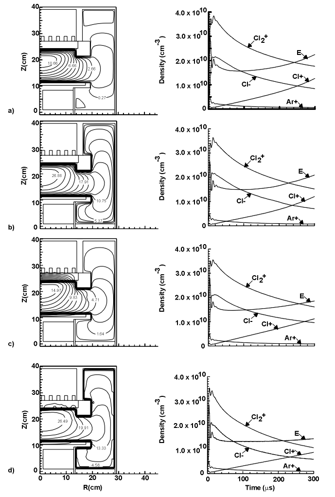
Fig. 1: Comparison between several different potential solvers. The left column contains pictures of electrostatic potential profiles, and the right column time-evolution of charged species densities. a) Ambipolar module without sheath model. b) Ambipolar module with sheath model. c) Poisson solver without sheath model. d) Poisson solver with sheath model.
References
1. M. J. Kushner, W. Z. Collison, M. J. Grapperhaus, J. P. Holland and J. S. Barnes, "A 3-dimensional Model for Inductively Coupled Plasma Etching Reactors: Azimuthal Symmetry and Coil Properties", J. Appl. Phys., 80, 1337 (1996).
*
This work is supported by the Semiconductor Research Corporation, the National Science Foundation, Advanced Research Projects Administration and the University of Wisconsin ERC for Plasma Aided Manufacturing.Last updated: January 27, 1998.